|
Component |
Purpose |
| 1 |
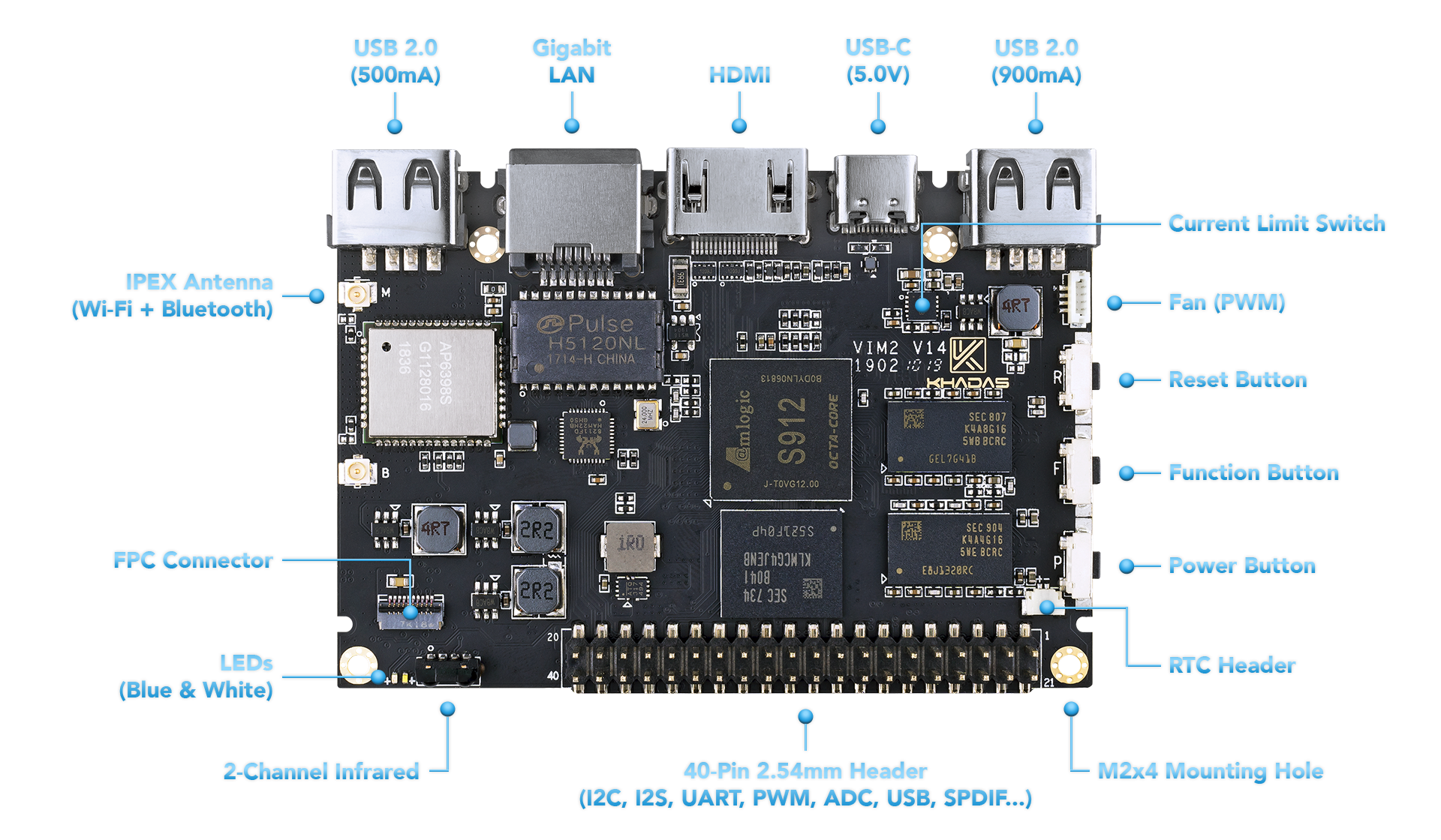
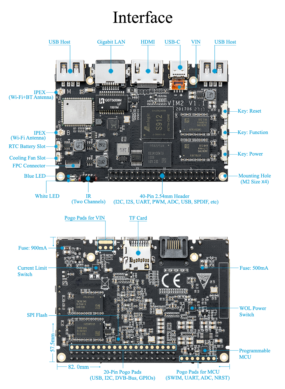
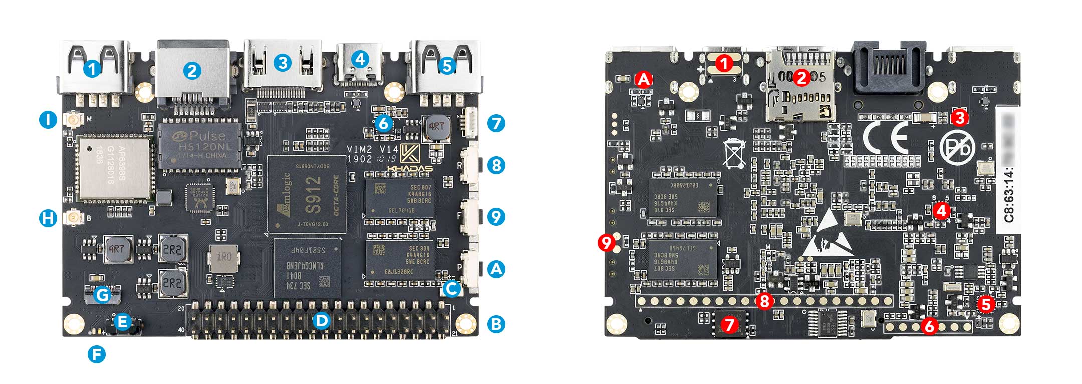
USB-A |
USB 2.0 speed, 500mA max output |
| 2 |
RJ-45 |
Gigabit Ethernet with Wake-On-LAN (WOL) |
| 3 |
HDMI |
HDMI 2.0a with CEC, 4K@60Hz |
| 4 |
USB-C |
USB 2.0 OTG and 5V power input, can be used for upgrading the OS |
| 5 |
USB-A |
USB 2.0 speed, 900mA max output |
| 6 |
Current Limit Switch |
Prevents damage to VIM2 during uneven loading conditions |
| 7 |
Fan Header |
4-wire fan header utilising pulse width modulation |
| 8 |
Reset Button |
Force reboot your VIM2 in the event of a system freeze |
| 9 |
Function Button |
Press this 3 times in 2 seconds to enter MaskROM mode |
| A |
Power Button |
This button turns on your VIM2 |
| B |
M2x4 Mounting Point |
For mounting to cases and heatsinks |
| C |
RTC Battery Header |
Header for attaching a battery for the real time clock |
| D |
40-Pin GPIO |
Learn how to access the GPIO from here, or use it to add a Toneboard |
| E |
Infrared Module |
2-channel infrared receiver for use with Khadas IR remote |
| F |
LEDs |
Status indicator LEDs |
| G |
FPC Connector |
10-pins, 0.5mm pitch, with I2C, IOs |
| H |
I-Pex Wi-Fi / Bluetooth Connector |
Wi-Fi / BT Antenna connector |
| I |
I-Pex Wi-Fi / Bluetooth Connector |
Wi-Fi / BT Antenna connector |
|
Component |
Purpose |
| 1 |
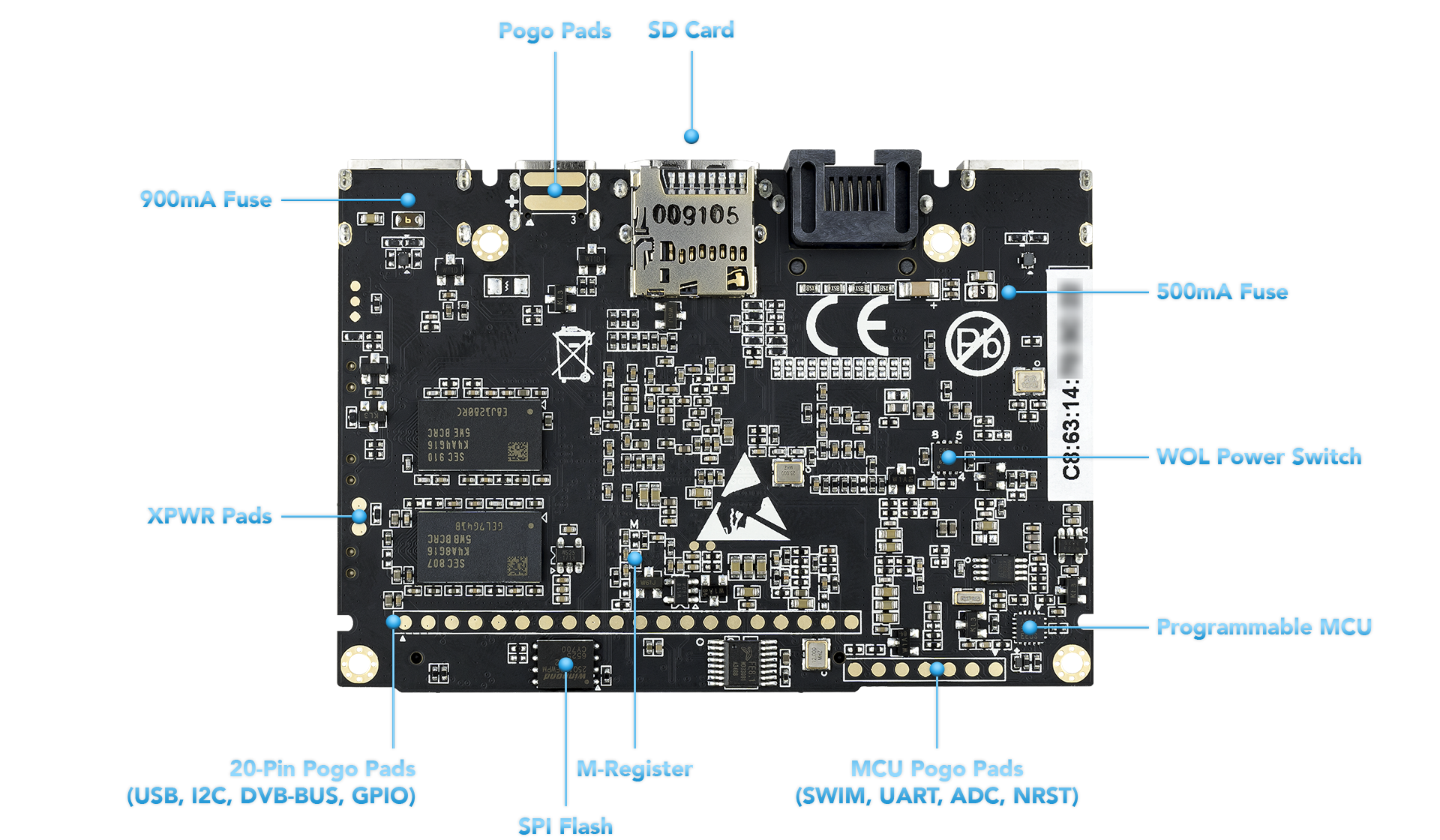
Pogo Pads |
External 5V power input, can be provided by vTV Board (DVB Tuner) |
| 2 |
Micro-SD Card Slot |
Boot alternative OSes via a micro-SD card, or just for extra storage |
| 3 |
500mA Fuse |
Fuse for the 500mA USB port |
| 4 |
WOL Switch |
Power switch activated via Wake-On-LAN |
| 5 |
MCU |
STM8S003 micro-controller with programmable EEPROM |
| 6 |
MCU Pogo Pads |
SWIM, UART, ADC, NRST |
| 7 |
SPI Flash |
Flash memory module that interfaces over SPI |
| 8 |
20-Pin Pogo Pads |
USB, I2C, DVB-Bus, IOs, for docking with the vTV Board (DVB Tuner) |
| 9 |
XPWR Pads |
Connect an external power switch using these pads |
| A |
900mA Fuse |
Fuse for the 900mA USB port |
| Colour |
Behaviour |
Meaning |
| Blue |
OFF |
Power source disconnected |
|
Solid ON |
Power source connected, SBC turned off |
| White |
OFF |
SBC turned off |
|
Solid ON |
SBC turned on |
| Red |
None |
None |
The above behaviours are default out-of-the-box, and can be altered by a user. For example the white LED can be made to blink or breathe. For more information on how to program them via your favourite OS (each OS is different), please consult with experts at forum.khadas.com.
| SIGNAL |
PIN |
PIN |
SIGNAL |
| 5V |
1 |
21 |
GND |
| 5V |
2 |
22 |
I2C_SCK_A |
| HUB_DM1 |
3 |
23 |
I2C_SDA_A |
| HUB_DP1 |
4 |
24 |
GND |
| GND |
5 |
25 |
I2C_SCK_B |
| GPIODV_21 |
6 |
26 |
I2C_SDA_B |
| GPIODV_22 |
7 |
27 |
3.3V |
| GPIODV_23 |
8 |
28 |
GND |
| GND |
9 |
29 |
I2S_SCLK |
| ADC_CH0 |
10 |
30 |
I2S_MCLK |
| 1.8V |
11 |
31 |
I2S_SDO |
| ADC_CH2 |
12 |
32 |
I2S_LRCK |
| SPDIF |
13 |
33 |
I2S_SDI |
| GND |
14 |
34 |
GND |
| UART_RX_AO_B |
15 |
35 |
PWM_D |
| UART_TX_AO_B |
16 |
36 |
RTC_CLK |
| GND |
17 |
37 |
GPIOH_5 |
| Linux_RX |
18 |
38 |
EXP_INT |
| Linux_TX |
19 |
39 |
GPIODV_13 |
| 3.3V |
20 |
40 |
GND |