Use Software PWM for servo control in WiringPi and WiringPi-Python.
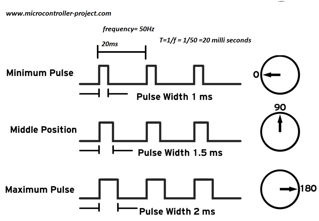
Principle of Servo Control The reference signal of the servo is 20ms in period and 1.5ms in width, and this corresponds to the servo’s middle position.
Different pulse widths correspond to different angles of the servo, and the range of pulse widths is 0.5ms to 2.5ms.
1
2
3
4
5
0.5ms -- 0 degree angle 1ms -- 45 degree angle 1.5ms -- 90 degree angle 2ms -- 135 degree angle 2.5ms -- 180 degree angle
The working principle of the 360-degree simulated-servo is the same as that of the servo.
1
2
3
0.5ms -- Counterclockwise/maximum speed 1.5ms -- Pause 2.5ms -- Clockwise/maximum speed
Demo Explanation
List available GPIO pins through gpio readall:
1
2
3
4
5
6
7
8
9
10
11
12
13
14
15
16
17
18
19
20
21
22
23
24
25
$ gpio readall +------+-----+----------+------+---+----+-- Model Khadas VIM3/3L --+----+---+------+----------+-----+------+ | GPIO | wPi | Name | Mode | V | DS | PU/PD | Physical | PU/PD | DS | V | Mode | Name | wPi | GPIO | +------+-----+----------+------+---+----+-------+----++----+-------+----+---+------+----------+-----+------+ | | | 5V | | | | | 1 || 21 | | | | | GND | | | | | | 5V | | | | | 2 || 22 | P/U | | 1 | IN | PIN.A15 | 6 | 475 | | | | USB_DM | | | | | 3 || 23 | P/U | | 1 | IN | PIN.A14 | 7 | 474 | | | | USB_DP | | | | | 4 || 24 | | | | | GND | | | | | | GND | | | | | 5 || 25 | P/U | | 1 | ALT0 | PIN.AO2 | 8 | 498 | | | | MCU3V3 | | | | | 6 || 26 | P/U | | 1 | ALT0 | PIN.AO3 | 9 | 499 | | | | MCUNRST | | | | | 7 || 27 | | | | | 3V3 | | | | | | MCUSWIM | | | | | 8 || 28 | | | | | GND | | | | | | GND | | | | | 9 || 29 | P/D | | 0 | IN | PIN.A1 | 10 | 461 | | | 18 | ADC0 | | | | | 10 || 30 | P/D | | 0 | IN | PIN.A0 | 11 | 460 | | | | 1V8 | | | | | 11 || 31 | P/D | | 0 | IN | PIN.A3 | 12 | 463 | | | 19 | ADC1 | | | | | 12 || 32 | P/D | | 0 | IN | PIN.A2 | 13 | 462 | | 506 | 1 | PIN.AO10 | ALT3 | 0 | | P/U | 13 || 33 | P/D | | 0 | IN | PIN.A4 | 14 | 464 | | | | GND3 | | | | | 14 || 34 | | | | | GND | | | | 433 | 2 | PIN.H6 | IN | 0 | | P/D | 15 || 35 | P/D | | 0 | ALT3 | PWM-F | 15 | 432 | | 434 | 3 | PIN.H7 | IN | 0 | | P/D | 16 || 36 | | | | | RTC | | | | | | GND | | | | | 17 || 37 | P/D | | 0 | OUT | PIN.H4 | 16 | 431 | | 497 | 4 | PIN.AO1 | ALT0 | 1 | | P/U | 18 || 38 | | | | | MCU-FA1 | | | | 496 | 5 | PIN.AO0 | ALT0 | 1 | | P/U | 19 || 39 | P/D | | 0 | IN | PIN.Z15 | 17 | 426 | | | | 3V3 | | | | | 20 || 40 | | | | | GND | | | +------+-----+----------+------+---+----+-------+----++----+-------+----+---+------+----------+-----+------+
Pin is configured as a normal IO output.
Simulate PWM and control through the softPwmCreate() and softPwmWrite() functions.
WiringPi Demo Source Code
The servo switches back and forth between 180 degrees, 90 degrees, and 0 degrees. The switching interval is 3 seconds to switch once, and the period is 9 seconds.
The analog servo rotates clockwise, pauses rotation and rotates backward counterclockwise to switch back and forth, the switching interval is 3 seconds to switch once, and the period is 9 seconds.
1 2 3 4 5 6 7 8 9 10 11 12 13 14 15 16 17 18 19 20 #include <wiringPi.h> #include <softPwm.h> int Pin = 16 ;int main () { wiringPiSetup(); pinMode(Pin, OUTPUT); softPwmCreate(Pin, 0 , 200 ); while (1 ){ softPwmWrite(Pin, 25 ); delay(3000 ); softPwmWrite(Pin, 15 ); delay(3000 ); softPwmWrite(Pin, 5 ); delay(3000 ); } return 0 ; }
Compile:
1 $ gcc -o SoftPwm SoftPwm.c -lwiringPi -lpthread -lrt -lm -lcrypt
WiringPi-Python Demo
The servo switches between 180 degrees, 90 degrees and 0 degrees successively, and the time interval is 3 seconds.
The analog servo switches between clockwise rotation, pause rotation and counterclockwise rotation, and the time interval is 3s.
1
2
3
4
5
6
7
8
9
10
11
12
13
14
15
16
17
18
import wiringpi as GPIOPWM_PIN = 16 PWM_OUTPUT = 1 GPIO.wiringPiSetup() GPIO.pinMode(PWM_PIN, PWM_OUTPUT) GPIO.softPwmCreate(PWM_PIN, 0 , 200 ) GPIO.softPwmWrite(PWM_PIN, 25 ) GPIO.delay(3000 ) GPIO.softPwmWrite(PWM_PIN, 15 ) GPIO.delay(3000 ) GPIO.softPwmWrite(PWM_PIN, 5 ) GPIO.delay(3000 )
