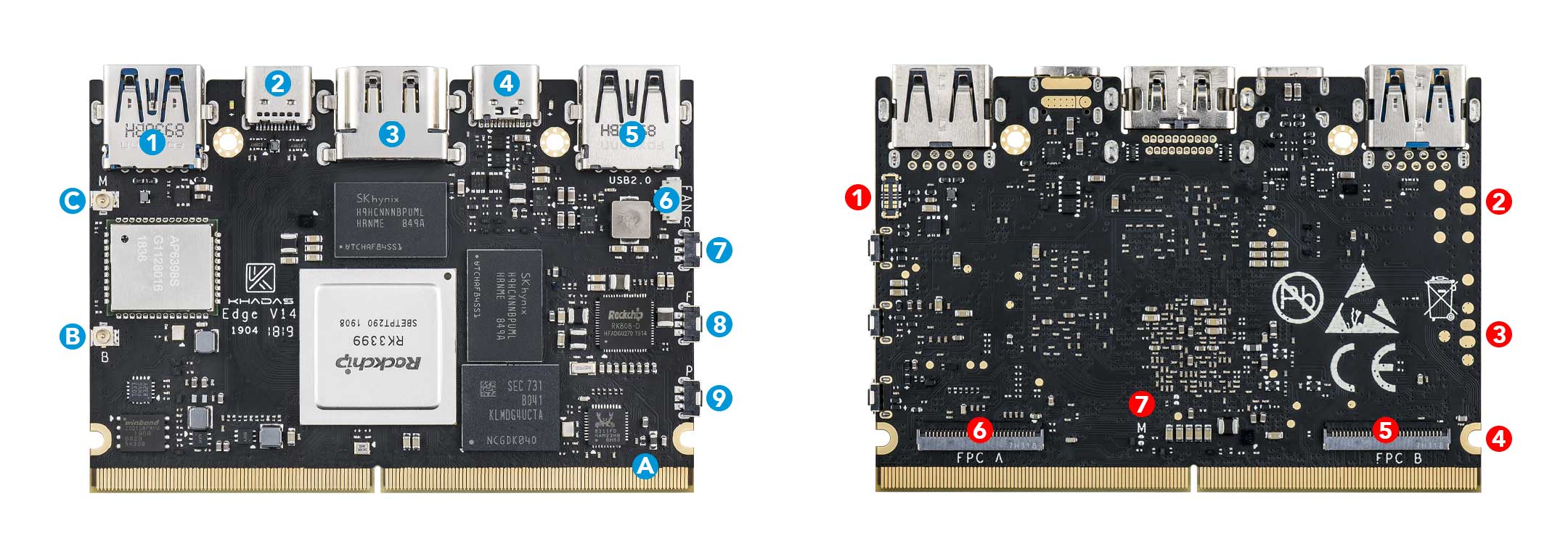
|
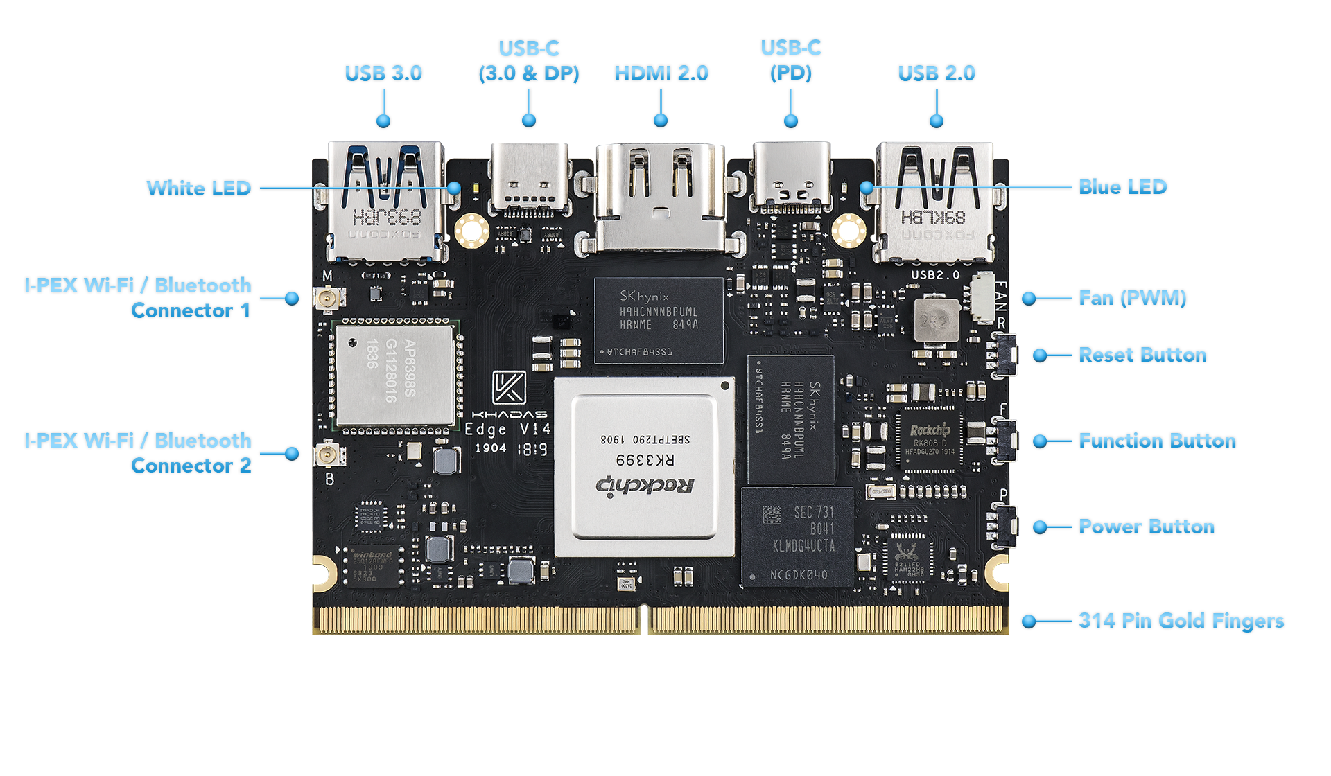
Component |
Purpose |
| 1 |
USB-A |
USB 3.0 speeds |
| 2 |
USB-C |
USB 3.0, Display Port v1.2, with 5-20V input (USB power delivery), can be used for upgrading the OS |
| 3 |
HDMI 2.0 |
Type-A Female, up to 4K@60Hz, HDCP 2.2 |
| 4 |
USB-C |
USB-C port with 5-20V input (USB power delivery) |
| 5 |
USB-A |
USB 2.0 speeds |
| 6 |
Fan Header |
4-wire fan header utilising pulse width modulation |
| 7 |
Reset Button |
Force reboot your Edge in the event of a system freeze |
| 8 |
Function Button |
Press this 3 times in 2 seconds to enter MaskROM mode |
| 9 |
Power Button |
This button turns on your Edge |
| A |
314-Pin Gold Fingers |
For docking with expansion boards such as the Captain |
| B |
I-Pex Wi-Fi / Bluetooth Connector |
Connect Wi-Fi / Bluetooth antennas |
| C |
I-Pex Wi-Fi / Bluetooth Connector |
Connect Wi-Fi / Bluetooth antennas |
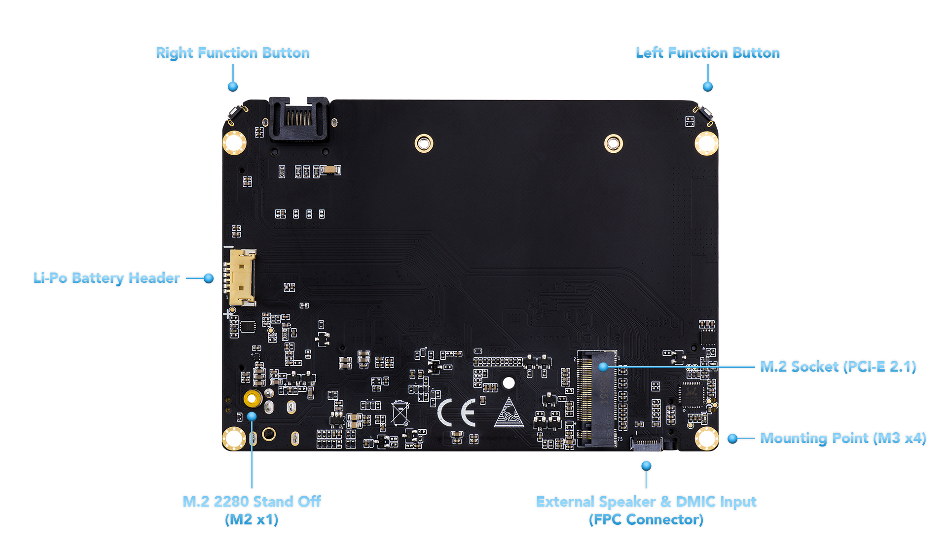
|
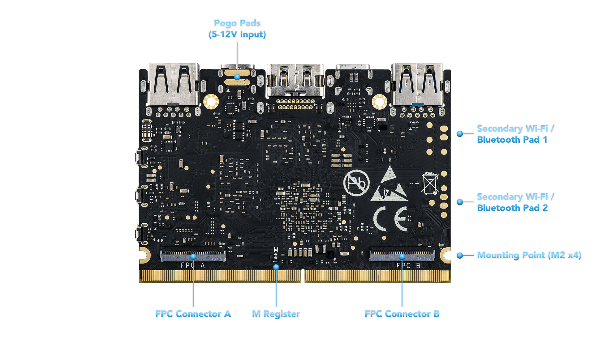
Component |
Purpose |
| 1 |
Li-Po Battery Connector |
For connecting Lithium Polymer batteries |
| 2 |
Secondary Wi-Fi / Bluetooth Pad |
Extra pad for mounting Wi-Fi / Bluetooth antennas |
| 3 |
Secondary Wi-Fi / Bluetooth Pad |
Extra pad for mounting Wi-Fi / Bluetooth antennas |
| 4 |
M2x4 Mounting Point |
For mounting a heatsink or carrier board |
| 5 |
FPC Connector B |
10-Pins, 0.5mm Pitch, USB, I2S(8ch), I2C, MCU IOs |
| 6 |
FPC Connector A |
10-Pins, 0.5mm Pitch, UART, I2C, SPI, SDMMC, ADC, PWM, IOs. To add GPIO, use Edge IO |
| 7 |
M-Register |
Allows the EMMC to enter MaskROM mode |
| Colour |
Behaviour |
Meaning |
| Blue |
OFF |
Power source disconnected |
|
Solid ON |
Power source connected, SBC turned off |
| White |
OFF |
SBC turned off |
|
Solid ON |
SBC turned on |
| Red |
None |
None |
The above behaviours are default out-of-the-box, and can be altered by a user. For example the white LED can be made to blink or breathe. For more information on how to program them via your favourite OS (each OS is different), please consult with experts at forum.khadas.com.
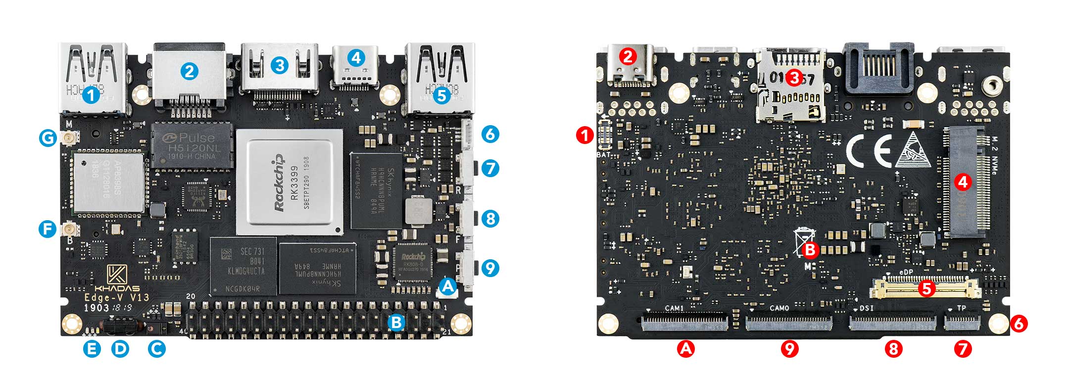
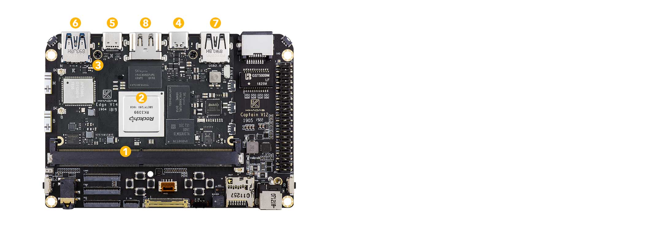
|
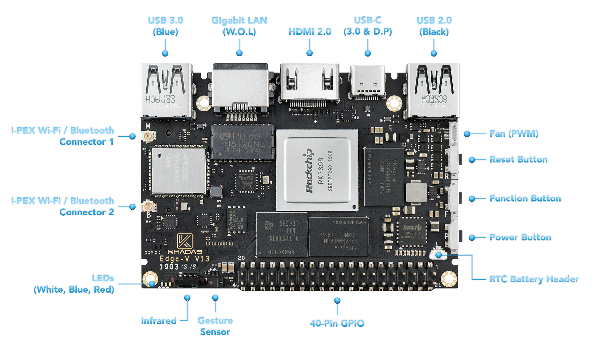
Component |
Purpose |
| 1 |
USB-A |
USB 3.0, blue colour |
| 2 |
RJ-45 |
Gigabit Ethernet with Wake-On-LAN (WOL) |
| 3 |
HDMI |
Type-A Female, up to 4K@60Hz, HDCP 2.2 |
| 4 |
USB-C |
USB 3.0, Display Port v1.2, can be used for upgrading the OS |
| 5 |
USB-A |
USB 2.0, black colour |
| 6 |
Fan Header |
4-wire fan header utilising pulse width modulation |
| 7 |
Reset Button |
Force reboot your Edge-V in the event of a system freeze |
| 8 |
Function Button |
Press this 3 times in 2 seconds to enter MaskROM mode |
| 9 |
Power Button |
This button turns on your Edge-V |
| A |
RTC Battery Header |
Header for attaching a battery for the real time clock |
| B |
40-Pin GPIO |
Learn how to access GPIO here, or use it to add a Toneboard |
| C |
Gesture Sensor |
Control your Edge-V with a hand-wave |
| D |
Infrared Module |
2-channel infrared receiver for use with Khadas IR remote |
| E |
LEDs |
Status indicator LEDs |
| F |
I-Pex Wi-Fi / Bluetooth Connector |
Wi-Fi / BT Antenna connector |
| G |
I-Pex Wi-Fi / Bluetooth Connector |
Wi-Fi / BT Antenna connector |
| Colour |
Behaviour |
Meaning |
| Blue |
OFF |
Power source disconnected |
|
Solid ON |
Power source connected, SBC turned off |
| White |
OFF |
SBC turned off |
|
Solid ON |
SBC turned on |
| Red |
None |
None |
The above behaviours are default out-of-the-box, and can be altered by a user. For example the white LED can be made to blink or breathe. For more information on how to program them via your favourite OS (each OS is different), please consult with experts at forum.khadas.com.
| SIGNAL |
PIN |
PIN |
SIGNAL |
| 5V |
1 |
21 |
GND |
| 5V |
2 |
22 |
SPI3_RXD/I2C0_SCK/GPIO1_C0 |
| HOST1_DM |
3 |
23 |
SPI3_TXD/I2C0_SDA/GPIO1_B7 |
| HOST1_DP |
4 |
24 |
GND |
| GND |
5 |
25 |
I2C2_SCL/GPIO2_A1 |
| MCU_TX |
6 |
26 |
I2C2_SDA/GPIO2_A0 |
| MCU_NRST |
7 |
27 |
3.3V |
| MCU_SWIM |
8 |
28 |
GND |
| GND |
9 |
29 |
I2S0_SCLK/GPIO3_D0 |
| ADC_IN2 |
10 |
30 |
I2S_CLK/GPIO4_A0 |
| 1.8V |
11 |
31 |
I2S0_SDO0/GPIO3_D7 |
| ADC_IN3 |
12 |
32 |
2S0_LRCK_TX/GPIO3_D2 |
| SPDIF/GPIO3_C0 |
13 |
33 |
I2S0_SDI0/GPIO3_D3 |
| GND |
14 |
34 |
GND |
| SPI3_CS/GPIO1_C2 |
15 |
35 |
I2S0_SDI3SDO1/GPIO3_D6 |
| SPI3_CLK/GPIO1_C1 |
16 |
36 |
2S0_SDI2SDO2/GPIO3_D5 |
| GND |
17 |
37 |
I2S0_SDI1SDO3/GPIO3_D4 |
| Linux_RX |
18 |
38 |
I2S0_LRCK_RX/GPIO3_D1 |
| Linux_TX |
19 |
39 |
MCU_PA1 |
| 3.3V |
20 |
40 |
GND |
|
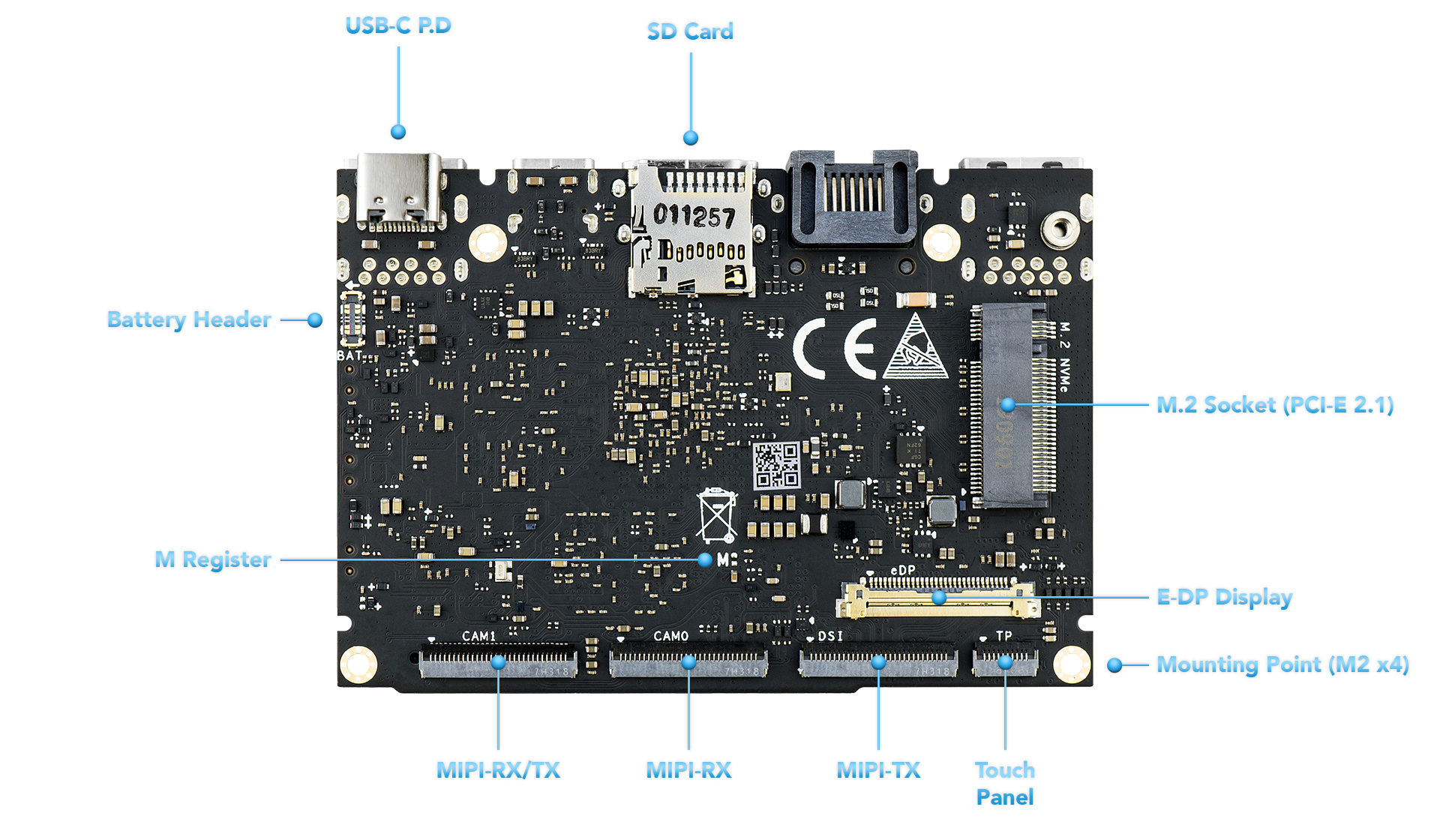
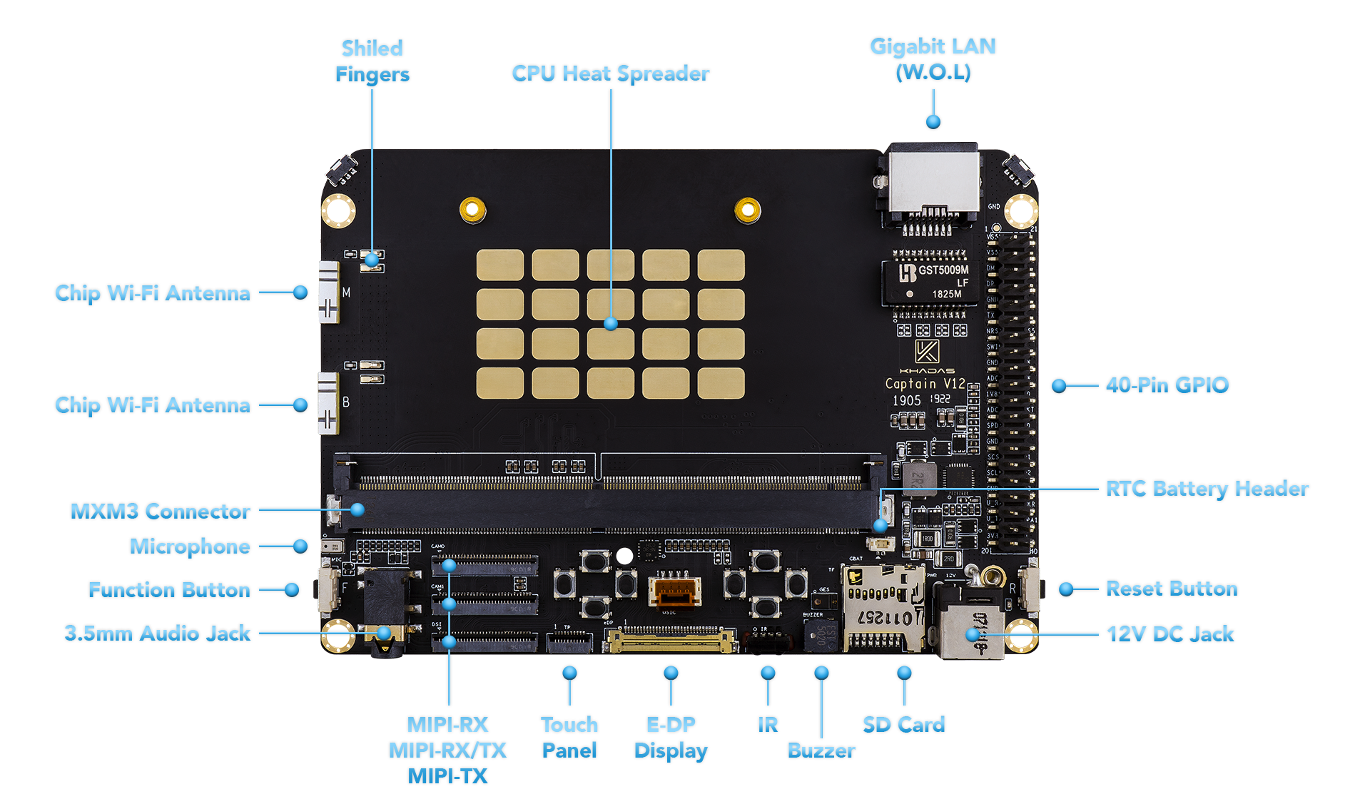
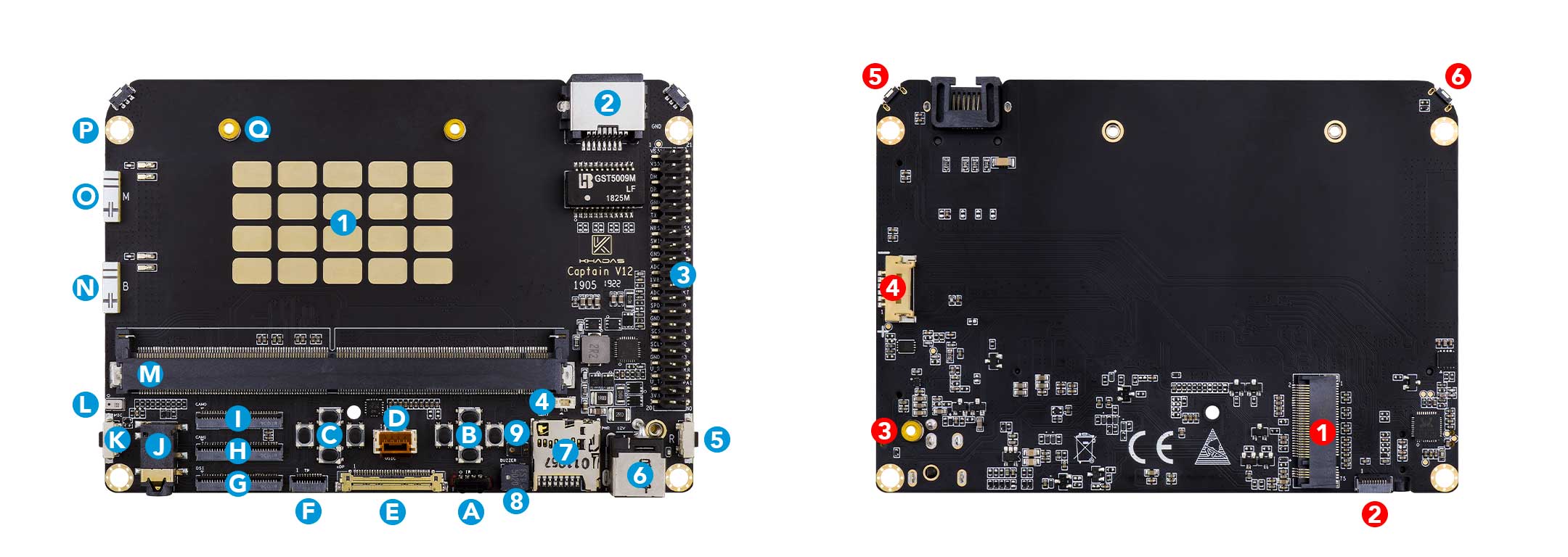
Component |
Purpose |
| 1 |
RK3399 SoC Heat Spreader |
Metallic layer for reducing heat concentration |
| 2 |
RJ-45 |
Gigabit Ethernet port with Wake-On-LAN (WOL) |
| 3 |
40-Pin GPIO |
Learn how to access the GPIO here |
| 4 |
RTC Header |
For connecting an external button battery for the real-time clock |
| 5 |
Reset Button |
Forcefully reboot Edge+Captain if your system freezes |
| 6 |
12V DC Barrel Jack |
Alternative 12V DC power input, see power priority |
| 7 |
Micro-SD Card Slot |
Boot additional OSes via Micro-SD, or just for extra storage |
| 8 |
Buzzer |
Produces simple sounds |
| 9 |
Gesture Sensor |
Control your Edge+Captain with a hand-wave |
| A |
IR Receiver |
2-channel infrared module, for use with the Khadas IR remote |
| B |
Right Game Pad |
For games, use with the Kap Case |
| C |
Left Game Pad |
For games, use with the Kap Case |
| D |
USIC |
Legacy USB-bus, unpopular |
| E |
E-DP Display |
For connecting to external displays via E-DP |
| F |
Touch Panel |
For accepting touch-input |
| G |
MIPI-TX |
MIPI-DSI header for connecting LCD screens |
| H |
MIPI-RX/TX |
Configurable MIPI-CSI/DSI header |
| I |
MIPI-RX |
For connecting to MIPI-CSI cameras |
| J |
3.5mm Audio Jack |
Audio output, works with the Kap Case |
| K |
Function Button |
For entering upgrade mode |
| L |
Microphone |
Audio input |
| M |
MXM3 Connector |
For docking with the Edge |
| N |
Wi-Fi / Bluetooth Chip Antenna |
Wi-Fi and BT antenna |
| O |
Wi-Fi / Bluetooth Chip Antenna |
Wi-Fi and BT antenna |
| P |
M3 Clearance Hole |
For mounting and cases, such as the Kap Case |
| Q |
M2 Threaded Stand-Off |
For mounting the Edge |
| Colour |
Behaviour |
Meaning |
| Blue |
OFF |
Power source disconnected |
|
Solid ON |
Power source connected, SBC turned off |
| White |
OFF |
SBC turned off |
|
Solid ON |
SBC turned on |
| Red |
None |
None |
The above behaviours are default out-of-the-box, and can be altered by a user. For example the white LED can be made to blink or breathe. For more information on how to program them via your favourite OS (each OS is different), please consult with experts at forum.khadas.com.
| SIGNAL |
PIN |
PIN |
SIGNAL |
| 5V |
1 |
21 |
GND |
| 5V |
2 |
22 |
SPI3_RXD/I2C0_SCK/GPIO1_C0 |
| HOST1_DM |
3 |
23 |
SPI3_TXD/I2C0_SDA/GPIO1_B7 |
| HOST1_DP |
4 |
24 |
GND |
| GND |
5 |
25 |
I2C2_SCL/GPIO2_A1 |
| MCU_TX |
6 |
26 |
I2C2_SDA/GPIO2_A0 |
| MCU_NRST |
7 |
27 |
3.3V |
| MCU_SWIM |
8 |
28 |
GND |
| GND |
9 |
29 |
I2S0_SCLK/GPIO3_D0 |
| ADC_IN2 |
10 |
30 |
I2S_CLK/GPIO4_A0 |
| 1.8V |
11 |
31 |
I2S0_SDO0/GPIO3_D7 |
| ADC_IN3 |
12 |
32 |
2S0_LRCK_TX/GPIO3_D2 |
| SPDIF/GPIO3_C0 |
13 |
33 |
I2S0_SDI0/GPIO3_D3 |
| GND |
14 |
34 |
GND |
| SPI3_CS/GPIO1_C2 |
15 |
35 |
I2S0_SDI3SDO1/GPIO3_D6 |
| SPI3_CLK/GPIO1_C1 |
16 |
36 |
2S0_SDI2SDO2/GPIO3_D5 |
| GND |
17 |
37 |
I2S0_SDI1SDO3/GPIO3_D4 |
| Linux_RX |
18 |
38 |
I2S0_LRCK_RX/GPIO3_D1 |
| Linux_TX |
19 |
39 |
MCU_PA1 |
| 3.3V |
20 |
40 |
GND |