|
Component |
Purpose |
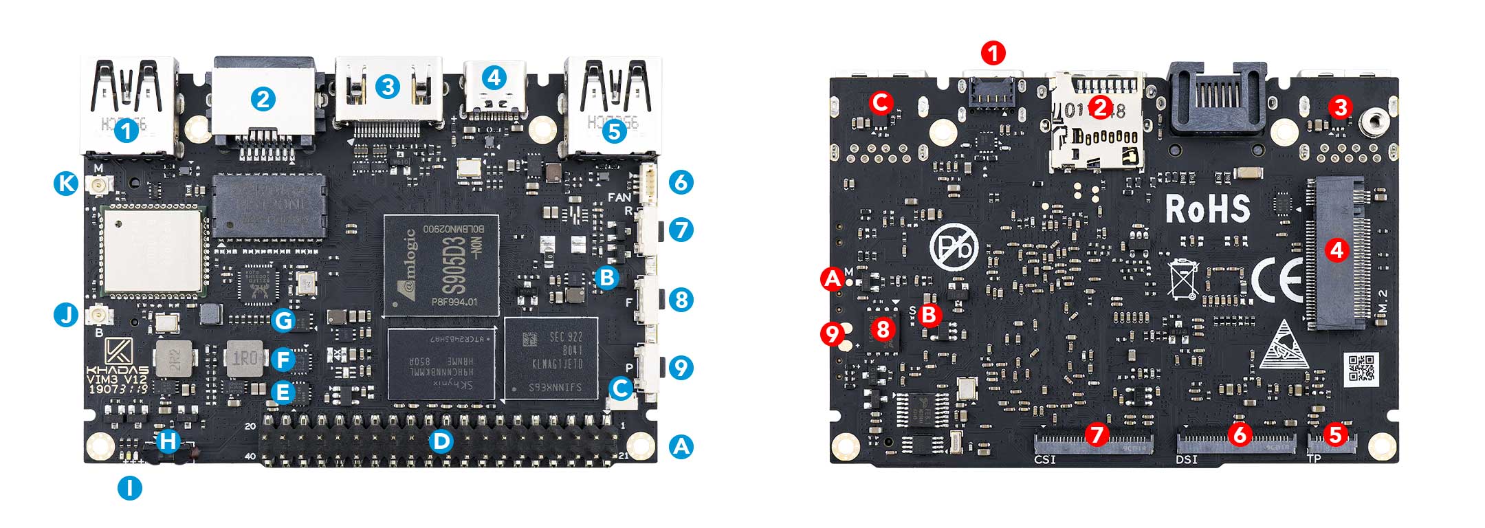
| 1 |
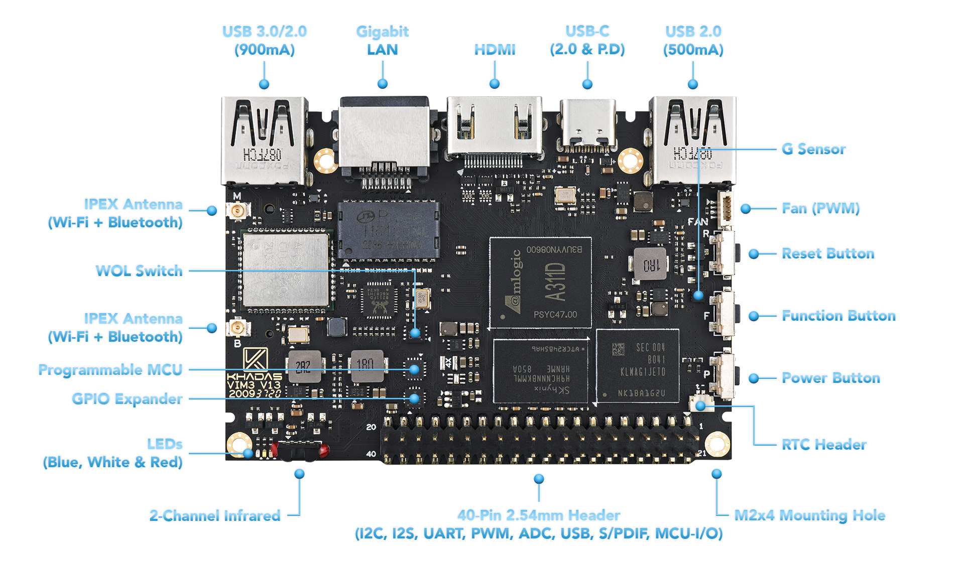
USB-A |
USB 3.0 port that swaps to 2.0 when PCI-E is active, 900mA output |
| 2 |
RJ-45 |
Gigabit LAN port that supports Wake-On-LAN |
| 3 |
HDMI |
HDMI port supporting CEC |
| 4 |
USB-C |
USB-C port with USB power delivery (5-20V input) and 2.0 speeds, can be used for upgrading the OS |
| 5 |
USB-A |
USB 2.0 port that supports 500mA output |
| 6 |
Fan Header |
4-wire fan header utilising pulse width modulation |
| 7 |
Reset Button |
Force reboot your VIM3 in the event of a system freeze |
| 8 |
Function Button |
Press this 3 times in 2 seconds to enter MaskROM mode |
| 9 |
Power Button |
This button turns on your VIM3 |
| A |
M2 Hole |
M2 clearance holes for a case, or adding a heatsink |
| B |
G-Sensor |
3-axis accelerometer |
| C |
RTC Header |
A header for connecting a real-time clock (button) battery |
| D |
40-Pin GPIO |
General input/output pins for VIM3’s SoC, or plugging-in a Toneboard |
| E |
GPIO Expander |
Increases VIM3’s available I/O beyond what A311D can provide |
| F |
MCU |
STM8S003 micro-controller with programmable EEPROM |
| G |
WOL Switch |
Power switch activated via Wake-On-LAN |
| H |
Infrared Module |
2-channel infrared receiver for the Khadas IR remote |
| I |
LEDs |
Indicator LEDs |
| J |
IPEX Antenna |
Wi-Fi and Bluetooth antenna connector |
| K |
IPEX Antenna |
Wi-Fi and Bluetooth antenna connector |
|
Component |
Purpose |
| 1 |
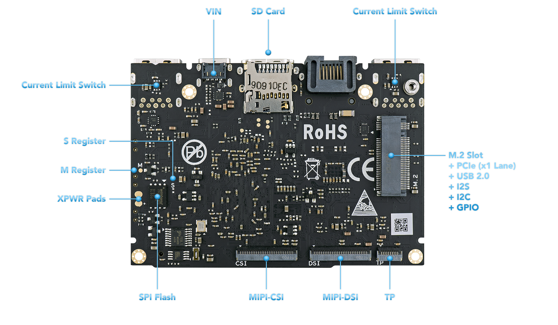
VIN |
5-12V power input, supports Power-Over-Ethernet via M2X Extension |
| 2 |
Micro-SD Slot |
Molex Slot, spec version 2.x/3.x/4.x (SDSC/SDHC/SDXC) |
| 3 |
Current Limit Switch |
Prevents damage to VIM3 due to faulty loading conditions |
| 4 |
M.2 Slot |
PCIe 2.0 (x1 lane), supports M.2 2280 NVMe SSDs |
| 5 |
TP |
10-pin 0.5mm pitch FPC connector for touch input |
| 6 |
MIPI-DSI |
30-pin, 0.5mm pitch FPC connector for 4-lane 1080P displays |
| 7 |
MIPI-CSI |
30-pin, 0.5mm pitch, 4-lane, dual cameras, 8MP image signal processing |
| 8 |
SPI Flash |
Flash memory module that interfaces over SPI |
| 9 |
XPWR Pads |
Connect an external power switch using these pads |
| A |
M-Register |
Allows the EMMC to enter MaskROM mode |
| B |
S-Register |
Allows the SPI Flash to enter MaskROM mode |
| Colour |
Behaviour |
Meaning |
| Blue |
OFF |
Power source disconnected |
|
Solid ON |
Power source connected, SBC turned off |
| White |
OFF |
SBC turned off |
|
Solid ON |
SBC turned on |
| Red |
None |
None |
The above behaviours are default out-of-the-box, and can be altered by a user. For example the white LED can be made to blink or breathe. For more information on how to program them via your favourite OS (each OS is different), please consult with experts at forum.khadas.com.
| SIGNAL |
PIN |
PIN |
SIGNAL |
| 5V |
1 |
21 |
GND |
| 5V |
2 |
22 |
I2C_M3_SCL |
| USB_DM |
3 |
23 |
I2C_M3_SDA |
| USB_DP |
4 |
24 |
GND |
| GND |
5 |
25 |
I2C_AO_SCK |
| VCC_MCU |
6 |
26 |
I2C_AO_SDA |
| MCU_NRST |
7 |
27 |
3.3V |
| MCU_SWIM |
8 |
28 |
GND |
| GND |
9 |
29 |
I2SB_SCLK |
| ADC_CH0 |
10 |
30 |
I2S_MCLK0 |
| 1.8V |
11 |
31 |
I2SB_SDO |
| ADC_CH3 |
12 |
32 |
I2SB_LRCK |
| SPDIF_OUT |
13 |
33 |
I2SB_SDI |
| GND |
14 |
34 |
GND |
| UARTC_RX |
15 |
35 |
PWM_F |
| UARTC_TX |
16 |
36 |
RTC_CLK |
| GND |
17 |
37 |
GPIOH_4 |
| Linux_RX |
18 |
38 |
MCU_PA1 |
| Linux_TX |
19 |
39 |
GPIODZ_15 |
| 3.3V |
20 |
40 |
GND |
|
Component |
Purpose |
| 1 |
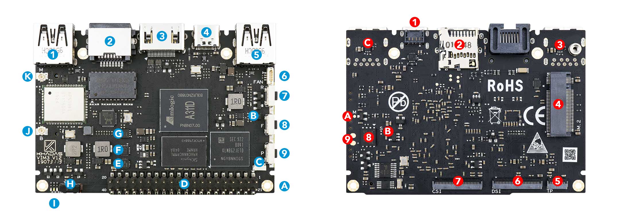
USB-A |
USB 3.0 port that swaps to 2.0 when PCI-E is active, 900mA output |
| 2 |
RJ-45 |
Gigabit LAN port that supports Wake-On-LAN |
| 3 |
HDMI |
HDMI port supporting CEC |
| 4 |
USB-C |
USB-C port with USB power delivery (5-20V input) and 2.0 speeds, can be used for upgrading the OS |
| 5 |
USB-A |
USB 2.0 port that supports 500mA output |
| 6 |
Fan Header |
4-wire fan header utilising pulse width modulation |
| 7 |
Reset Button |
Force reboot your VIM3L in the event of a system freeze |
| 8 |
Function Button |
Press this 3 times in 2 seconds to enter MaskROM mode |
| 9 |
Power Button |
This button turns on your VIM3L |
| A |
M2 Hole |
M2 clearance holes for a case, or adding a heatsink |
| B |
G-Sensor |
3-axis accelerometer |
| C |
RTC Header |
A header for connecting a real-time clock (button) battery |
| D |
40-Pin GPIO |
General input/output pins for VIM3L’s SoC, or plugging-in a Toneboard |
| E |
GPIO Expander |
Increases VIM3L’s available I/O beyond what S905D3 can provide |
| F |
MCU |
STM8S003 micro-controller with programmable EEPROM |
| G |
WOL Switch |
Power switch activated via Wake-On-LAN |
| H |
Infrared Module |
2-channel infrared receiver for the Khadas IR remote |
| I |
LEDs |
Indicator LEDs |
| J |
IPEX Antenna |
Wi-Fi and Bluetooth antenna connector |
| K |
IPEX Antenna |
Wi-Fi and Bluetooth antenna connector |
|
Component |
Purpose |
| 1 |
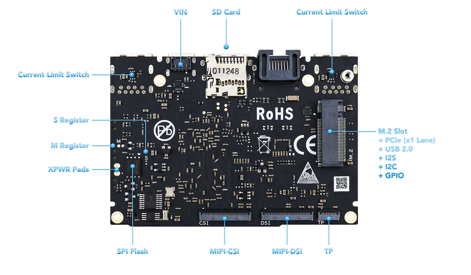
VIN |
5-12V power input, supports Power-Over-Ethernet via M2X Extension |
| 2 |
Micro-SD Slot |
Molex Slot, spec version 2.x/3.x/4.x (SDSC/SDHC/SDXC) |
| 3 |
Current Limit Switch |
Prevents damage to VIM3L due to faulty loading conditions |
| 4 |
M.2 Slot |
PCIe 2.0 (x1 lane), supports M.2 2280 NVMe SSDs |
| 5 |
TP |
10-pin 0.5mm pitch FPC connector for touch input |
| 6 |
MIPI-DSI |
30-pin, 0.5mm pitch FPC connector for 4-lane 1080P displays |
| 7 |
MIPI-CSI |
30-pin, 0.5mm pitch, 4-lane, single camera, no image signal processor |
| 8 |
SPI Flash |
Flash memory module that interfaces over SPI |
| 9 |
XPWR Pads |
Connect an external power switch using these pads |
| A |
M-Register |
Allows the EMMC to enter MaskROM mode |
| B |
S-Register |
Allows the SPI Flash to enter MaskROM mode |
| C |
Current Limit Switch |
Prevents damage to VIM3L due to faulty loading conditions |
| Colour |
Behaviour |
Meaning |
| Blue |
OFF |
Power source disconnected |
|
Solid ON |
Power source connected, SBC turned off |
| White |
OFF |
SBC turned off |
|
Solid ON |
SBC turned on |
| Red |
None |
None |
The above behaviours are default out-of-the-box, and can be altered by a user. For example the white LED can be made to blink or breathe. For more information on how to program them via your favourite OS (each OS is different), please consult with experts at forum.khadas.com.
| SIGNAL |
PIN |
PIN |
SIGNAL |
| 5V |
1 |
21 |
GND |
| 5V |
2 |
22 |
I2C_M3_SCL |
| USB_DM |
3 |
23 |
I2C_M3_SDA |
| USB_DP |
4 |
24 |
GND |
| GND |
5 |
25 |
I2C_AO_SCK |
| VCC_MCU |
6 |
26 |
I2C_AO_SDA |
| MCU_NRST |
7 |
27 |
3.3V |
| MCU_SWIM |
8 |
28 |
GND |
| GND |
9 |
29 |
I2SB_SCLK |
| ADC_CH0 |
10 |
30 |
I2S_MCLK0 |
| 1.8V |
11 |
31 |
I2SB_SDO |
| ADC_CH3 |
12 |
32 |
I2SB_LRCK |
| SPDIF_OUT |
13 |
33 |
I2SB_SDI |
| GND |
14 |
34 |
GND |
| UARTC_RX |
15 |
35 |
PWM_F |
| UARTC_TX |
16 |
36 |
RTC_CLK |
| GND |
17 |
37 |
GPIOH_4 |
| Linux_RX |
18 |
38 |
MCU_PA1 |
| Linux_TX |
19 |
39 |
GPIODZ_15 |
| 3.3V |
20 |
40 |
GND |