This document mainly introduces how to use software PWM on WiringPi and WiringPi-Python.
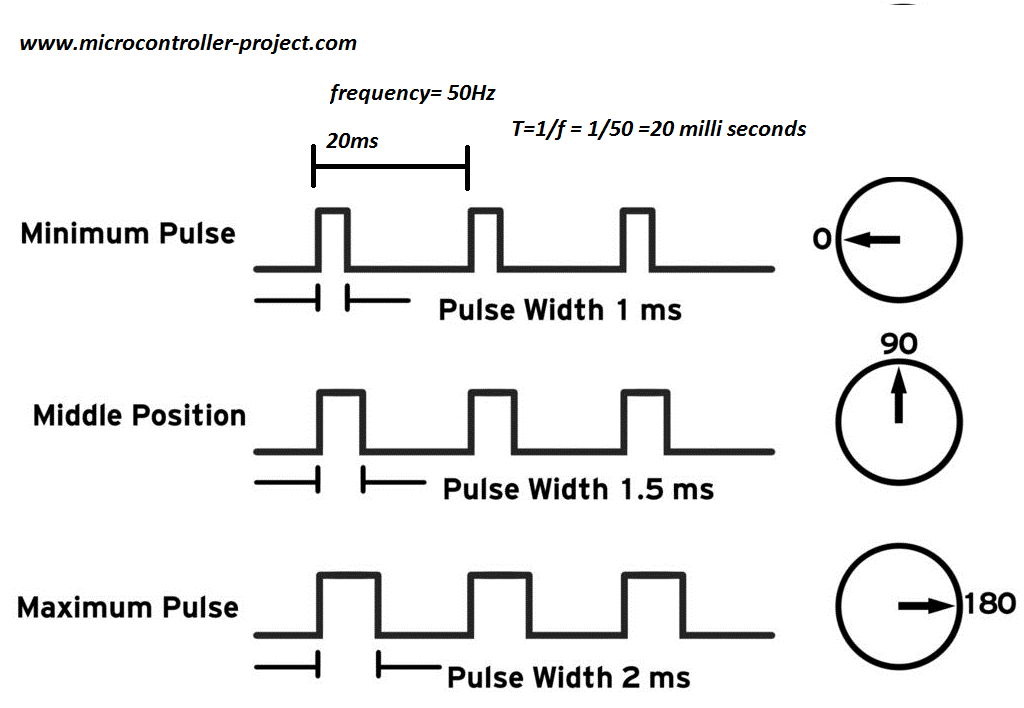
1. SoftPWM Servo Principle of servo control The reference signal of the servo is 20ms in period and 1.5ms in width. Corresponds to the middle position of the servo.
Different pulse widths correspond to different angles of the servo, and the corresponding range of pulse widths is 0.5 to 2.5ms.
1
2
3
4
5
0.5ms -- 0 degree angle 1ms -- 45 degree angle 1.5ms -- 90 degree angle 2ms -- 135 degree angle 2.5ms -- 180 degree angle
The working principle of the 360-degree angle simulation servo is the same as that of the servo.
1
2
3
0.5ms -- Counterclockwise/maximum speed 1.5ms -- Pause 2.5ms -- Clockwise/maximum speed
Source code compilation and demonstration Explanation
Check the available pins through gpio readall
1
2
3
4
5
6
7
8
9
10
11
12
13
14
15
16
17
18
19
20
21
22
23
24
25
$ gpio readall +------+-----+----------+------+---+----+-- Model Khadas VIM3/3L --+----+---+------+----------+-----+------+ | GPIO | wPi | Name | Mode | V | DS | PU/PD | Physical | PU/PD | DS | V | Mode | Name | wPi | GPIO | +------+-----+----------+------+---+----+-------+----++----+-------+----+---+------+----------+-----+------+ | | | 5V | | | | | 1 || 21 | | | | | GND | | | | | | 5V | | | | | 2 || 22 | P/U | | 1 | IN | PIN.A15 | 6 | 475 | | | | USB_DM | | | | | 3 || 23 | P/U | | 1 | IN | PIN.A14 | 7 | 474 | | | | USB_DP | | | | | 4 || 24 | | | | | GND | | | | | | GND | | | | | 5 || 25 | P/U | | 1 | ALT0 | PIN.AO2 | 8 | 498 | | | | MCU3V3 | | | | | 6 || 26 | P/U | | 1 | ALT0 | PIN.AO3 | 9 | 499 | | | | MCUNRST | | | | | 7 || 27 | | | | | 3V3 | | | | | | MCUSWIM | | | | | 8 || 28 | | | | | GND | | | | | | GND | | | | | 9 || 29 | P/D | | 0 | IN | PIN.A1 | 10 | 461 | | | 18 | ADC0 | | | | | 10 || 30 | P/D | | 0 | IN | PIN.A0 | 11 | 460 | | | | 1V8 | | | | | 11 || 31 | P/D | | 0 | IN | PIN.A3 | 12 | 463 | | | 19 | ADC1 | | | | | 12 || 32 | P/D | | 0 | IN | PIN.A2 | 13 | 462 | | 506 | 1 | PIN.AO10 | ALT3 | 0 | | P/U | 13 || 33 | P/D | | 0 | IN | PIN.A4 | 14 | 464 | | | | GND3 | | | | | 14 || 34 | | | | | GND | | | | 433 | 2 | PIN.H6 | IN | 0 | | P/D | 15 || 35 | P/D | | 0 | ALT3 | PWM-F | 15 | 432 | | 434 | 3 | PIN.H7 | IN | 0 | | P/D | 16 || 36 | | | | | RTC | | | | | | GND | | | | | 17 || 37 | P/D | | 0 | OUT | PIN.H4 | 16 | 431 | | 497 | 4 | PIN.AO1 | ALT0 | 1 | | P/U | 18 || 38 | | | | | MCU-FA1 | | | | 496 | 5 | PIN.AO0 | ALT0 | 1 | | P/U | 19 || 39 | P/D | | 0 | IN | PIN.Z15 | 17 | 426 | | | | 3V3 | | | | | 20 || 40 | | | | | GND | | | +------+-----+----------+------+---+----+-------+----++----+-------+----+---+------+----------+-----+------+
Pin is configured as normal IO output
Simulate PWM and control through the softPwmCreate() and softPwmWrite() functions
WiringPi source code and compilation
The servo switches back and forth between 1800 degrees, 90 degrees, and 0 degrees. The switching interval is 3S to switch once, and the period is 9S.
The analog servo rotates clockwise, pauses rotation and counterclockwise rotation to switch back and forth, the switching interval is 3S to switch once, and the period is 9S.
1 2 3 4 5 6 7 8 9 10 11 12 13 14 15 16 17 18 19 20 #include <wiringPi.h> #include <softPwm.h> int Pin = 16 ;int main () { wiringPiSetup(); pinMode(Pin, OUTPUT); softPwmCreate(Pin, 0 , 200 ); while (1 ){ softPwmWrite(Pin, 25 ); delay(3000 ); softPwmWrite(Pin, 15 ); delay(3000 ); softPwmWrite(Pin, 5 ); delay(3000 ); } return 0 ; }
Compile command
1 $ gcc -o SoftPwm SoftPwm.c -lwiringPi -lpthread -lrt -lm -lcrypt
WiringPi-Python source code
The servo switches between 180 degrees, 90 degrees and 0 degrees successively, and the time interval is 3S.
The analog servo is switched between clockwise rotation, pause rotation and counterclockwise rotation, and the time interval is 3S.
1
2
3
4
5
6
7
8
9
10
11
12
13
14
15
16
17
18
import wiringpi as GPIOPWM_PIN = 16 PWM_OUTPUT = 1 GPIO.wiringPiSetup() GPIO.pinMode(PWM_PIN, PWM_OUTPUT) GPIO.softPwmCreate(PWM_PIN, 0 , 200 ) GPIO.softPwmWrite(PWM_PIN, 25 ) GPIO.delay(3000 ) GPIO.softPwmWrite(PWM_PIN, 15 ) GPIO.delay(3000 ) GPIO.softPwmWrite(PWM_PIN, 5 ) GPIO.delay(3000 )
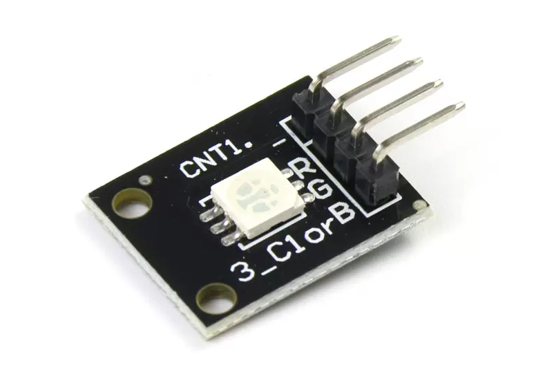
2. PWM RGG LED Principle of Control
The module is controlled by 3 PWMs, each of which controls one of the three-color channels. By controlling the luminous intensity of the three channels, different colors are synthesized.
Source code compilation and demonstration Running effect, the red light, green light, blue light and white light will each be on for 3 seconds.
Explanation
Check the available pins through gpio readall
1
2
3
4
5
6
7
8
9
10
11
12
13
14
15
16
17
18
19
20
21
22
23
24
25
$ gpio readall +------+-----+----------+------+---+----+-- Model Khadas VIM3/3L --+----+---+------+----------+-----+------+ | GPIO | wPi | Name | Mode | V | DS | PU/PD | Physical | PU/PD | DS | V | Mode | Name | wPi | GPIO | +------+-----+----------+------+---+----+-------+----++----+-------+----+---+------+----------+-----+------+ | | | 5V | | | | | 1 || 21 | | | | | GND | | | | | | 5V | | | | | 2 || 22 | P/U | | 1 | IN | PIN.A15 | 6 | 475 | | | | USB_DM | | | | | 3 || 23 | P/U | | 1 | IN | PIN.A14 | 7 | 474 | | | | USB_DP | | | | | 4 || 24 | | | | | GND | | | | | | GND | | | | | 5 || 25 | P/U | | 1 | ALT0 | PIN.AO2 | 8 | 498 | | | | MCU3V3 | | | | | 6 || 26 | P/U | | 1 | ALT0 | PIN.AO3 | 9 | 499 | | | | MCUNRST | | | | | 7 || 27 | | | | | 3V3 | | | | | | MCUSWIM | | | | | 8 || 28 | | | | | GND | | | | | | GND | | | | | 9 || 29 | P/D | | 0 | IN | PIN.A1 | 10 | 461 | | | 18 | ADC0 | | | | | 10 || 30 | P/D | | 0 | IN | PIN.A0 | 11 | 460 | | | | 1V8 | | | | | 11 || 31 | P/D | | 0 | IN | PIN.A3 | 12 | 463 | | | 19 | ADC1 | | | | | 12 || 32 | P/D | | 0 | IN | PIN.A2 | 13 | 462 | | 506 | 1 | PIN.AO10 | ALT3 | 0 | | P/U | 13 || 33 | P/D | | 0 | IN | PIN.A4 | 14 | 464 | | | | GND3 | | | | | 14 || 34 | | | | | GND | | | | 433 | 2 | PIN.H6 | IN | 0 | | P/D | 15 || 35 | P/D | | 0 | ALT3 | PWM-F | 15 | 432 | | 434 | 3 | PIN.H7 | IN | 0 | | P/D | 16 || 36 | | | | | RTC | | | | | | GND | | | | | 17 || 37 | P/D | | 0 | OUT | PIN.H4 | 16 | 431 | | 497 | 4 | PIN.AO1 | ALT0 | 1 | | P/U | 18 || 38 | | | | | MCU-FA1 | | | | 496 | 5 | PIN.AO0 | ALT0 | 1 | | P/U | 19 || 39 | P/D | | 0 | IN | PIN.Z15 | 17 | 426 | | | | 3V3 | | | | | 20 || 40 | | | | | GND | | | +------+-----+----------+------+---+----+-------+----++----+-------+----+---+------+----------+-----+------+
Pin is configured as normal IO output
Simulate PWM and control through the softPwmCreate() and softPwmWrite() functions
WiringPi source code and compilation 1 2 3 4 5 6 7 8 9 10 11 12 13 14 15 16 17 18 19 20 21 22 23 24 25 26 27 28 29 30 31 32 33 34 35 36 37 #include <wiringPi.h> #include <softPwm.h> int Pin_Blue = 10 ;int Pin_Red = 11 ;int Pin_Green = 12 ;int main () { wiringPiSetup(); pinMode(Pin_Blue, OUTPUT); pinMode(Pin_Red, OUTPUT); pinMode(Pin_Green, OUTPUT); softPwmCreate(Pin_Blue, 0 , 255 ); softPwmCreate(Pin_Red, 0 , 255 ); softPwmCreate(Pin_Green, 0 , 255 ); printf ("Red LED\n" ); softPwmWrite(Pin_Red, 255 ); softPwmWrite(Pin_Green, 0 ); softPwmWrite(Pin_Blue, 0 ); delay(3000 ); printf ("Green LED\n" ); softPwmWrite(Pin_Red, 0 ); softPwmWrite(Pin_Green, 255 ); softPwmWrite(Pin_Blue, 0 ); delay(3000 ); printf ("Blue LED\n" ); softPwmWrite(Pin_Red, 0 ); softPwmWrite(Pin_Green, 0 ); softPwmWrite(Pin_Blue, 255 ); delay(3000 ); printf ("White LED\n" ); softPwmWrite(Pin_Red, 255 ); softPwmWrite(Pin_Green, 255 ); softPwmWrite(Pin_Blue, 255 ); delay(3000 ); return 0 ; }
Compile command
1 $ gcc -o SoftPwm SoftPwm.c -lwiringPi -lpthread -lrt -lm -lcrypt
WiringPi-Python source code 1 2 3 4 5 6 7 8 9 10 11 12 13 14 15 16 17 18 19 20 21 22 23 24 25 26 27 28 29 30 31 32 33 34 35 import wiringpi as GPIORED_PIN = 11 BLUE_PIN = 10 GREEN_PIN = 12 PWM_OUTPUT = 1 GPIO.wiringPiSetup() GPIO.pinMode(RED_PIN, PWM_OUTPUT) GPIO.softPwmCreate(RED_PIN, 0 , 255 ) GPIO.softPwmCreate(BLUE_PIN, 0 , 255 ) GPIO.softPwmCreate(GREEN_PIN, 0 , 255 ) print ("GED LED" )GPIO.softPwmWrite(RED_PIN, 255 ) GPIO.softPwmWrite(GREEN_PIN, 0 ) GPIO.softPwmWrite(BLUE_PIN, 0 ) GPIO.delay(3000 ) print ("Green LED" )GPIO.softPwmWrite(RED_PIN, 0 ) GPIO.softPwmWrite(GREEN_PIN, 255 ) GPIO.softPwmWrite(BLUE_PIN, 0 ) GPIO.delay(3000 ) print ("Blue LED" )GPIO.softPwmWrite(RED_PIN, 0 ) GPIO.softPwmWrite(GREEN_PIN, 0 ) GPIO.softPwmWrite(BLUE_PIN, 255 ) GPIO.delay(3000 ) print ("White LED" )GPIO.softPwmWrite(RED_PIN, 255 ) GPIO.softPwmWrite(GREEN_PIN, 255 ) GPIO.softPwmWrite(BLUE_PIN, 255 ) GPIO.delay(3000 )
You can try other colors by yourself, and different colors will be produced if you configure different PWMs.